

Creating A Multi-Beam Reflection Display Hologram
You are now going to use the real image of your final transmission hologram plate from your multi-beam transmission setup as the object scene in this multi-beam white light reflection display hologram setup. You're also going to use your multi-beam transmission setup for this reflection hologram setup, with a few changes. Figure 21a illustrates the setup if you want to hang your hologram on a wall and use overhead ceiling lighting. Later, in Figure 21c, I'll show you the setup if you want to hang your hologram on a wall and use underneath table based lighting. Figure 21b shows a close-up of H1, H2, and the real image positions.
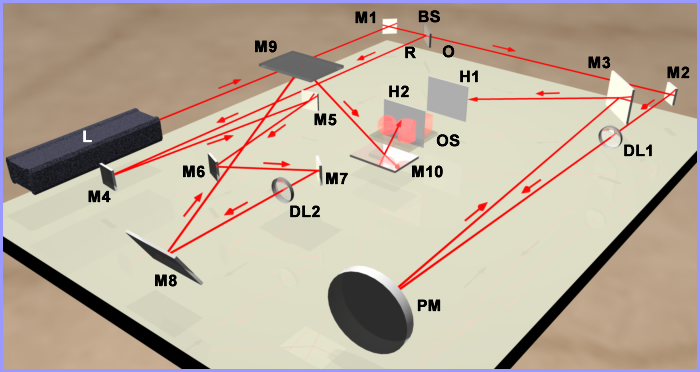
Figure 21a: Multi-beam white light reflection display hologram setup for overhead reconstruction.
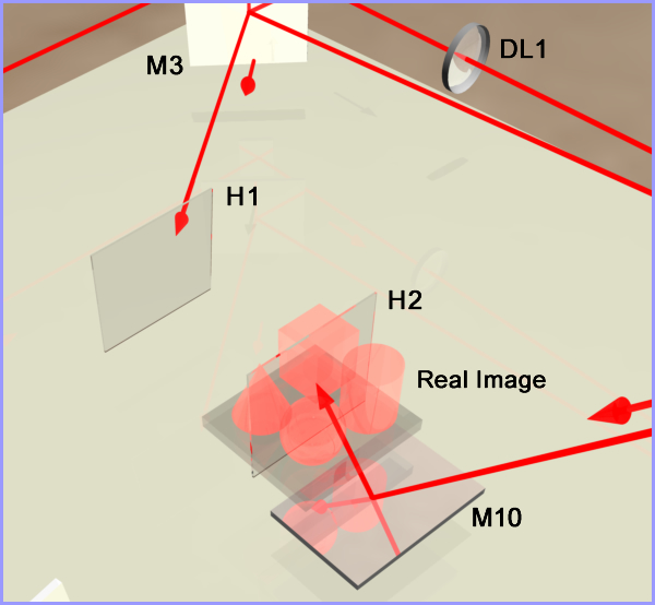
Figure 21b: Close-up of H1, H2, and real image.
There are a number of things that have changed in this setup from the multi-beam transmission setup:
- The original object scene has been completely removed.
- The labeling of the plate holder has been changed to H1 instead of PH. In holography lingo, the transmission hologram projecting the real image is called H1 and the second plate holder for the reflection hologram recording plate is called H2.
- The object scene OS is now the projected real image from H1 and H2 is shown straddling the real image.
- I've switched the reference beam and object beam labeling. The transmission hologram's setup reference beam is now called the object beam O because it is now reconstructing the real image as the object scene for H2.
- The transmission hologram setup object beam is now called the reference beam R.
- Three additional mirrors (M8-M10) have been added to the new reference beam.
- A second plate holder has been added to hold the recording plate for H2, the reflection hologram you're now going to make.
Changing the Polarization Orientation
The very first thing you need to do is to change the polarization orientation from horizontal to vertical because the new reference beam will be incident on recording plate H2 from underneath. The incident angle should again be 56 degrees. There are three ways you can do this:
- You can insert a 1/2λ waveplate into the laser beam between the laser and mirror M1, and rotate the waveplate until the polarization is oriented vertically as indicated by your polarized sunglasses testing lens downstream of the waveplate. These waveplates are circular like lenses and can be mounted in a lens optical mount. You need to determine the orientation of the waveplate that gives you the polarization direction you need before you mount it in the optical mount. This approach is the easiest and the best because you do not have to make any adjustments downstream in the new object beam. I highly recommend this approach even though the cost of the waveplate is $370.
- Rotate the laser 90 degrees.
- Insert or remove the two mirror assembly that switches the beam from horizontal to vertical orientation or vice versa.
If you choose one of the last two, then you will need to realign the beam along the new object path. This will also nullify my statement in the above note about not moving the laser or mirror M1. You do not need to move the beamsplitter or any of the optics in the new object beam path to make this polarization orientation change at this time. Let's take some examples to help clarify what you need to do at this point if you're not using a waveplate.
Example 1: In the three setups you've done up to this point, you needed a horizontally polarized beam since the reference beam was incident on the side of the recording plate. Also, I made the assumption that the laser was manufactured so it had vertical polarization at the output aperture. You either had to rotate the laser 90 degrees on its side or use the two mirror assembly to re-orientate the beam from vertical to horizontal. If you rotated the laser, then all you need to do is rotate it 90 degrees back to its upright position. If you used the two mirror assembly, then you need to replace this assembly with mirror M1 only, with its center 9 inches above the table and you need to move the laser upward so that its output aperture beam is also at 9 inches above the table. Next, do the retro-reflection technique between the laser and M1.
Once you have the beam between the laser and M1 at 9 inches , you need to direct the beam from mirror M1 through the beamsplitter and downstream through all the optics in the new object beam path to the plate holder containing H1. This isn't too difficult. You may have to move M1 around on the table surface to facilitate this alignment and then you may have to turn mirror M2 and/or move diverging lens DL1 to get the hologram illuminated properly.
Example 2: If your laser was manufactured with horizontal polarization and of course that's how you used it for the first three setups, you'll either have to rotate the laser 90 degrees or insert the two mirror assembly to get vertical polarization. If you rotate the laser and keep mirror M1 where it was originally positioned for the three other setups, you probably will need to adjust the laser's output aperture beam to be 9 inches above the table and move the laser right or left and probably tilt the front up or down to hit M1 in its center. Then you can move mirror M1 around on the table surface to align the beam downstream through all the optics in the new object beam path to the plate holder containing H1.
If you decide to use the two mirror assembly, then you need to lower the laser output aperture and the first mirror to 7 inches and do the retro-reflection technique. Then insert the second mirror with its center at 9 inches and facing the beamsplitter. Send the beam from the first mirror to the second mirror as shown in Figure 15e. Now move and adjust the second mirror so it is aligned downstream along the new object beam path all the way to H1 and illuminates the hologram properly. You can now see why I highly recommend using a waveplate.
New Object Beam Changes
Once you have established a beam with vertical polarization and the new object beam is aligned properly, remove the original object scene (actually, you could have done this before you set up your vertical polarization). Next, re-insert H1 in its plate holder and orientate the transmission hologram H1 so it is projecting its real image. You're now ready to make changes in the new reference beam.
Setting Up the Components in the New Reference Beam
- Mirrors M4 and M5 can stay where they were originally placed.
- Mirror M6 has been moved forward so it's reflected beam does not strike diverging lens DL2.
- You can now insert plate holder H2 into the setup in the position shown in Figure 21a. You should place another white screen in plate holder H2 so you can see the real image projected on the screen. Move the plate holder forward and backward relative to H1 to place the center of the real image straddling the screen. Make sure H2 seats squarely facing H1.
- Now, looking at Figure 21a, imagine a straight line running through mirror M8, mirror M7, plate holder H2, and plate holder H1. The center of all of these components should be aligned along this line and, of course, at a height of 9 inches . Mirrors M8, M9, and M10 should all be 5 inch x 7 inch x 1/4 inch thick in size. Mirror M7 can be changed to a smaller 1 inch x 1 inch x 1/8 inch thick mirror size.
- Place mirror M10 low on the table so it can reflect the beam from mirror M9 upward to the center of plate holder H2 at an angle of 56 degrees as shown in Figure 21b. Make sure it is centered along the imaginary line.
- Now insert mirror M9 about 20 inches above the table surface and centered along the imaginary line as shown in Figure 21a. You should use a table mount on each side of the mirror and attach two connectors to each table mount rod for inserting an additional length of an aluminum rod to extend the height of each table mount's rod. The Plexiglas mount for this mirror should have a short rod with a 1/4-20 bolt on the left and right sides of the mount for attaching to the left and right table mounts. This will insert stability with the height being so high. The 7 inch length of the mirror should be orientated to match the 5 inch length of the plate.
- You will need to tilt mirror M8 upward to direct the beam to M9.
- You will now probably need to move mirror M9 along the imaginary line while also adjusting the tilt angle of mirror M8 and mirror M10 to get the desired 56 degree angle. The closer M9 is to M10, the steeper the angle will be reflected from M10 to the plate holder. Keep the white screen in plate holder H2 while you make these adjustments so you can see the position of the laser beam dot which should be centered on the screen.
- Next, check the polarization between mirror M3 and H1, and also check it between mirror M10 and the screen. They should both be vertical. Since H1 is a finished processed hologram, the fact that the incident beam on H1 is now vertical instead of horizontal and from the side, is no longer relevant even if some internal interference patterns (extremely rare) may be seen in H1. The plate H1 will not show up in the image created in H2.
- Now measure the path lengths. The new object beam distance should include the distance from H1 to H2.
- The path length of the new reference beam path should be the only path adjusted to match the distance of the new object beam path. With the insertion of mirrors M8-M10, the path length of the new reference beam has substantially increased. Try to use mirror M5 to make this adjustment. You may have to move M4 closer toward M5. Keep M7 where it is. With all these mirrors being adjusted, you may have to realign the beam from M7 through M10.
- Once the path length is established for the new reference beam, insert diverging lens DL2 into the setup between mirror M7 and mirror M8. Move the lens between these two mirrors until you achieve uniform illumination on the screen in H2. You can use a 10x or 20x microscope objective or a plano- or double-concave lens with a -15 mm or -9 mm focal length.
- Now check the beam ratios. It should be 1.5:1 (1.5 to 1). Use the cosine function here.
- Take an exposure reading measuring only the reference beam. The solar cell should face the incident reference beam square on (perpendicular to the beam). Determine your exposure time and double it. You want to achieve an exposure density of 2 for a reflection hologram. Do not use the cosine function.
- Finally, you need to mask certain parts of the table to eliminate extraneous light at H2.
- Place a mask between the parabolic mirror PM and H2, close to PM, so H2 can't see the laser beam reflected off the surface of PM.
- Place masks upstream of both diverging lenses DL1 and DL2, close to each lens as you did for the multi-beam transmission hologram, to eliminate extraneous laser cavity noise.
- Place a mask between mirror M7 and H2, close to M7, so H2 can't see any reflections off the back side of M7 or beam dots on DL2 or mirror M8.
- You may also need additional masks to prevent H2 from seeing M1, BS, M3, M4, and M6.
- Finally, look through the plate holder H2 toward H1. You should be able to scan the area around H1 and see no other light sources. Also look from the H1 side of H2 towards and through H2 from various angles to see if you can see any reflections off mirrors or other extraneous light reflections.
- Put the white screen back in the plate holder and check both sides of the card for extraneous light.
Check the reference beam illumination again at H2 for uniform illumination and check that H1 is uniformly illuminated. Put your shutter in place. Go ahead with the recording procedure and processing. Check the density of your first recording and make exposure time corrections if needed. Make sure that when you put the plate in the H2 holder, the emulsion is facing H1. This means that when the hologram is illuminated as it hangs on a wall from overhead, the emulsion will face the viewer. This also allows the glass side of the bleached plate to be painted flat black for a much brighter image. Use the painting procedure described previously.
If you decide to place the image in H2 to be projected in front of the plate instead of straddling the plate, move H2 away from H1. If you want the image to be further behind the plate, move H2 closer to H1. Remember, though, that you can only move H2 so close to H1 without the reconstructing light for H1 hitting H2, which you don't want.
If you want your final white light reflection display hologram to be illuminated from underneath the plate with the illuminating light source on a table top, use the setup shown in Figure 21c.
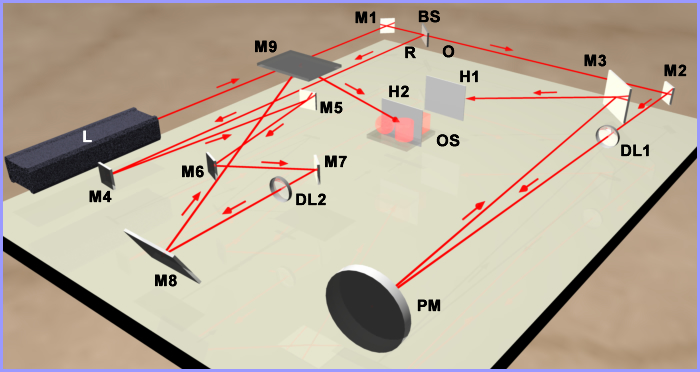
Figure 21c: Multi-beam white light reflection display hologram setup for underneath reconstruction.
A reflection hologram produces a monochromatic colored image. Since this hologram will be viewed with a white light source described in the next section, the color reconstructed in the image will depend on two factors:
- Whether the hologram is air dried or dried with heat after processing and after painting. If the hologram is air dried, the fringe shrinkage will be minimal and your image should be gold in color. Drying the hologram with heat shrinks the emulsion, which in turn, shrinks the interference fringes in the emulsion and causes the color of the image to shift toward green and blue.
- The angle of the reconstruction illumination. The greater the reconstruction angle is away from the plane's normal causes the image color to shift towards the blue end of the spectrum.
Home | Introduction | Overview | Optical Table | Environment | Laser | Beamsplitter |
Mirrors ⁄ Lenses | Table Mounts | Optic Mounts | Plate Holder | Objects ⁄ Scenes | Hard Copy | Resources
Home | Introduction | Vibrations | Processing | SB Transmission | Exposure |
Recording | SB Reflection | MB Transmission | MB Reflection | Lighting | Hardcopy | Resources